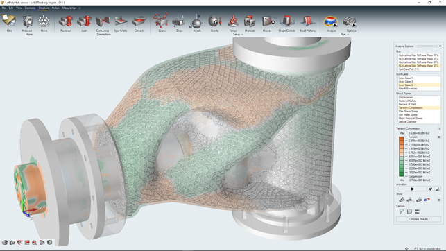
To convert this finalized shape to a part, right click its name in the Model Browser and select Convert Bodies to Parts.įinally, we can begin Boolean Operations. We want to subtract the first set of cylinders from the rest of the parts in the model. This indicates self-intersecting geometry and will not be a valid PolyNURBS surface. When doing this, watch out for areas of red appearing in the model. Simply click and drag vertices, edges, and faces of cages and watch how the shape changes. So, we will go through and finalize the PolyNURBS shape. We need another set of cylinders to represent the material that will surround the holes, so repeating the same process as above, we can create those.īefore we begin Boolean operations, we convert the PolyNURBS body to a part. These cylinders represent the holes for our bracket and will be removed via Boolean operations later. Now, we use the Push/Pull tool to extrude the faces of those circles. Once the lines are sketched, we click Transfer Sketch to create the circles as a new part in the model.Īfter renaming the part “Circles,” it shows up in the Model Browser and the associated circular surfaces now show up in the graphics area. Adding sketch entities will bring up an in-context menu to size them properly. Then, Altair Inspire will bring up a grid for sketching on. Select in the graphics window to set the plane going normal to the axis of our cylinders. We select the circle tool from the top menu, then we are prompted to create a new plane. Next, we’ll begin the process for our cylindrical holes. I can simply go back into the wrap tool and select the cage faces that are now more directly facing each other. Moving the mouse around the face will give you in-context options to move and rotate the face of that cage to orient it.Īs you can see from the screenshot above, I need to connect those two members of the part.

To change this, simply de-select whichever tool we are in (the wrap tool in our case) and select the face. Sometimes faces of a PolyNURBS cage are not facing the direction you want them to.


We continue creating wrap sections from the cage faces until we have an acceptable shape. Select a location on the edge of the cage face you want to split and a location on the opposite edge. There’s an option to split the whole cage or just a face. You can fit the faces to more manageable sizes using the split tool. Sometimes faces of the cage are too large for the next section of wrapping you wish to begin. Again, I have extruded the shape into the area that I want the cylindrical hole. To begin making the right side of the part, I select the long face of the second cage to start wrapping that direction.Ĭreating the desirable wrap cage takes some manipulation of the viewport but is as easy as just continuing to click. This is intentional.Įach face of a cage can be used for starting a new wrap feature. Note that we have made a protrusion into the cylindrical hole of the part. We will work our way to the left side of the part. Hover the mouse over the area, and a red preview of the initial cross section and a black box indicating the cage of the PolyNURBS shows up.Įach click generates a PolyNURBS cage. Since our part is symmetric about the center, we will start there. From there select the mesh from the graphics window and enter the parameters for the smoothing algorithm.įrom here we can begin “wrapping” the mesh with PolyNURBS by selecting the Wrap tool.

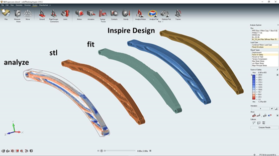
Use the PolyNURBS selection at the top of the screen to open the toolbar and Select smooth. It’s best to start by cleaning up sharp edges. I imported this part from SOLIDWORKS, but the same process stands for native Altair parts or otherwise. It’s my first real experience with Altir Inspire, so the goal of this blog is to show a few features of the PolyNURBS tool as we work our way through. The part pictured above is a bracket for a mountain bike rear suspension, an ideal candidate for topology studies. Uniquely, Altair Inspire not only performs topology analysis, but also includes a great PolyNURBS tool that excels at making the organic geometry we so desire. However, one of the main downsides to topology studies is that parts come out as a tessellated mess, like the one below: All three of these are great tools, and each has their own merits. Here at CATI we offer no less than 3 solutions that can accomplish just that Topology study in SOLIDWORKS Simulation Professional, Tosca from SIMULIA, and Altair Inspire. Today, it seems there are endless options for optimizing part geometry.


 0 kommentar(er)
